| Chapter III. WSN430 Schematic | ||
|---|---|---|
 |  | |
| Chapter III. WSN430 Schematic | ||
|---|---|---|
| | | |
Table of Contents
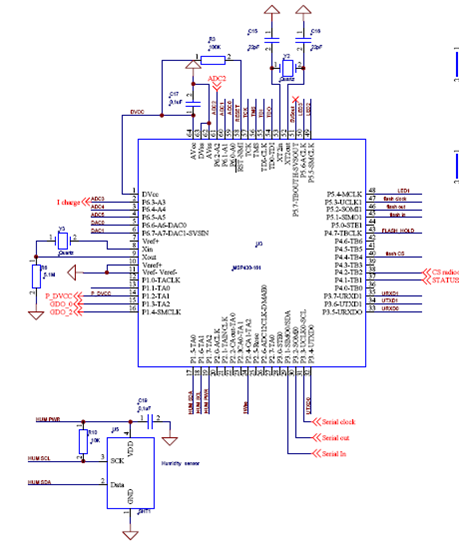
Figure III.1, “WSN430 schematic (MSP430)” gives the schematic of the microcontroller part of the WSN430 board. The complete file can be obtained from the Worldsens web site. For more information on the MSP430 microcontroler, the datasheet can be found at TI
The Texas Instruments MSP430 family of ultralow power microcontrollers consists of several devices featuring different sets of peripherals targeted for various applications. The architecture, combined with five low power modes is optimized to achieve extended battery life. The device features a powerful 16-bit RISC CPU, 16-bit registers, and constant generators that attribute to maximum code efficiency. The digitally controlled oscillator (DCO) allows wake-up from low-power modes to active mode in less than 6ms.
The MSP430f1611 is a microcontroller configuration with two built-in 16-bit timers, a fast 12-bit A/D converter, dual 12-bit D/A converter, two universal serial synchronous/asynchronous communication interfaces (USART), I2C, DMA, and 48 I/O pins. In addition, the MSP430f1611 offers extended RAM addressing for memory-intensive applications and large C-stack requirements.
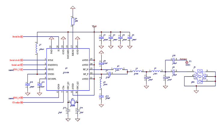
Figure III.2, “WSN430 schematic (CC1100)” gives the schematic of the RF part of the WSN430 board. The complete file can be obtained from the Worldsens web site. For more information on the CC1100 microcontroller, the datasheet can be found at TI
The CC1100 is sub-1 GHz radio frequency (RF) transceiver. The circuit is mainly intended for the ISM (Industrial, Scientific and Medical) and SRD (Short Range Device) frequency bands at 315, 433, 868, and 915 MHz, but can easily be programmed for operation at other frequencies in the 300-348 MHz, 400-464 MHz and 800-928 MHz bands.
The RF transceiver is integrated with a configurable baseband modem. The modem supports various modulation formats and has a configurable data rate of up to 500 kBaud. The CC1100 also provides hardware support for packet handling, data buffering, burst transmissions, clear channel assessment, link quality indication, and wake-on-radio.
The main operating parameters and the 64-byte transmit/receive FIFOs of the CC1100 are controlled via the SPI interface.
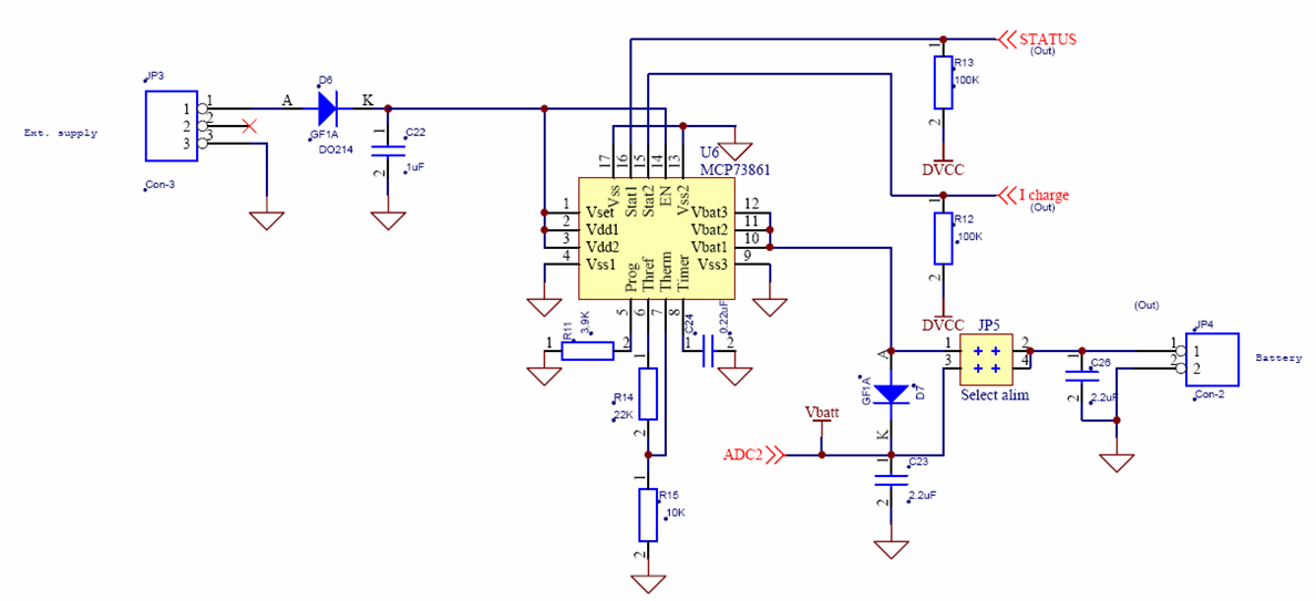
Figure III.3, “WSN430 schematic (MCP73861)” gives the schematic of the charge controller. The complete file can be obtained from the Worldsens web site. For more information on the MCP73861 linear charge management controller, the datasheet can be found at Microchip
The MCP73861 combines constant voltage, constant current regulation, cell preconditioning, cell temperature monitoring, advanced safety timers, automatic charge termination, and charge status and fault indication. The MCP73861 provides a charge management solution for single-cell Li-Ion and Li-Polymer applications.
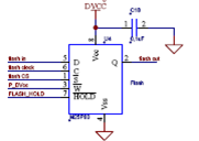
Figure III.4, “WSN430 schematic (M25P80)” gives the schematic of the flash memory. The complete file can be obtained from the Worldsens web site. For more information on the M25P80 flash memory, the datasheet can be found at ST .
The M25P80 is an 8 Mbit (1 Mbit x 8) Serial Flash memory, with advanced write protection mechanisms, accessed by the SPI bus.
The memory can be programmed 1 to 256 bytes at a time, using the Page Program instruction. The memory is organized as 16 sectors, each containing 256 pages. Each page is 256 bytes wide. Thus, the whole memory can be viewed as consisting of 4096 pages, or 1,048,576 bytes. The whole memory can be erased using the Bulk Erase instruction, or a sector at a time, using the Sector Erase instruction.
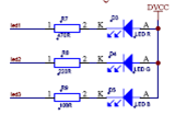
Figure III.5, “WSN430 schematic (LEDS)” gives the schematic of the three LEDs (green, red and blue). The complete file can be obtained from the Worldsens web site.
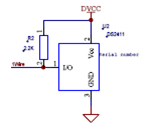
Figure III.6, “WSN430 schematic (DS2411)” gives the schematic of the unique identifier. The complete file can be obtained from the worldsens web site. For more information on the DS2411 Silicon Serial Number, the datasheet can be found at MAXIM
DS2411 provides an absolutely unique identity. The DS2411's registration number is a factory-lasered, 64-bit ROM that includes a unique 48-bit serial number, an 8-bit CRC, and an 8-bit family code (01h). Data is transferred serially through the 1-Wire protocol.
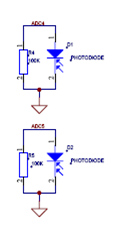
Figure III.7, “WSN430 schematic (SFH 2400 and SFH 2400)” gives the schematic of the photo diodes. The complete file can be obtained from the worldsens web site. For more informations on the DS2411 Silicon Serial Number, the datasheet can be found at OSRAM
SFH 2400 and SFH 2400 FA photodiodes are suitable for 400nm to 1100nm and from 750nm to 1100nm.
| | | |
| Chapter II. Introduction |  | Chapter IV. WSN430 Power |