Anti-dynamo theorems
Dynamo theory made a slow start. This is partly due to the structure of the equations of electromagnetism and their coupling with dynamics. For a conductor, the induction equation contains everything we need from the electromagnetic side. Conversely, the magnetic field leads to a Lorentz force acting on moving conductors. In principle, fast motion of conductors can lead to the spontaneous generation of a magnetic field, this is called dynamo action. It has been shown, in a series of articles due to Cowlings, that the flow field necessary to start and maintain dynamo action must break some symmetries. A planar flow (with two non-zero cartesian components) cannot maintain a dynamo, a flow in a sphere with non radial component cannot maintain a dynamo. Also, perhaps the most famous of these theorems, an axisymmetric magnetic field cannot be maintained by dynamo action.
However, these anti-dynamo theorems are valid only when the electrical conductivity is isotropic. I have been working with Franck Plunian on this topic and we have obtained analytical solutions of simple dynamos with anisotropic electrical conductivity: sliding plates PDF and rotating cylinder inside a stator PDF.
Theoretical Anisotropic Models
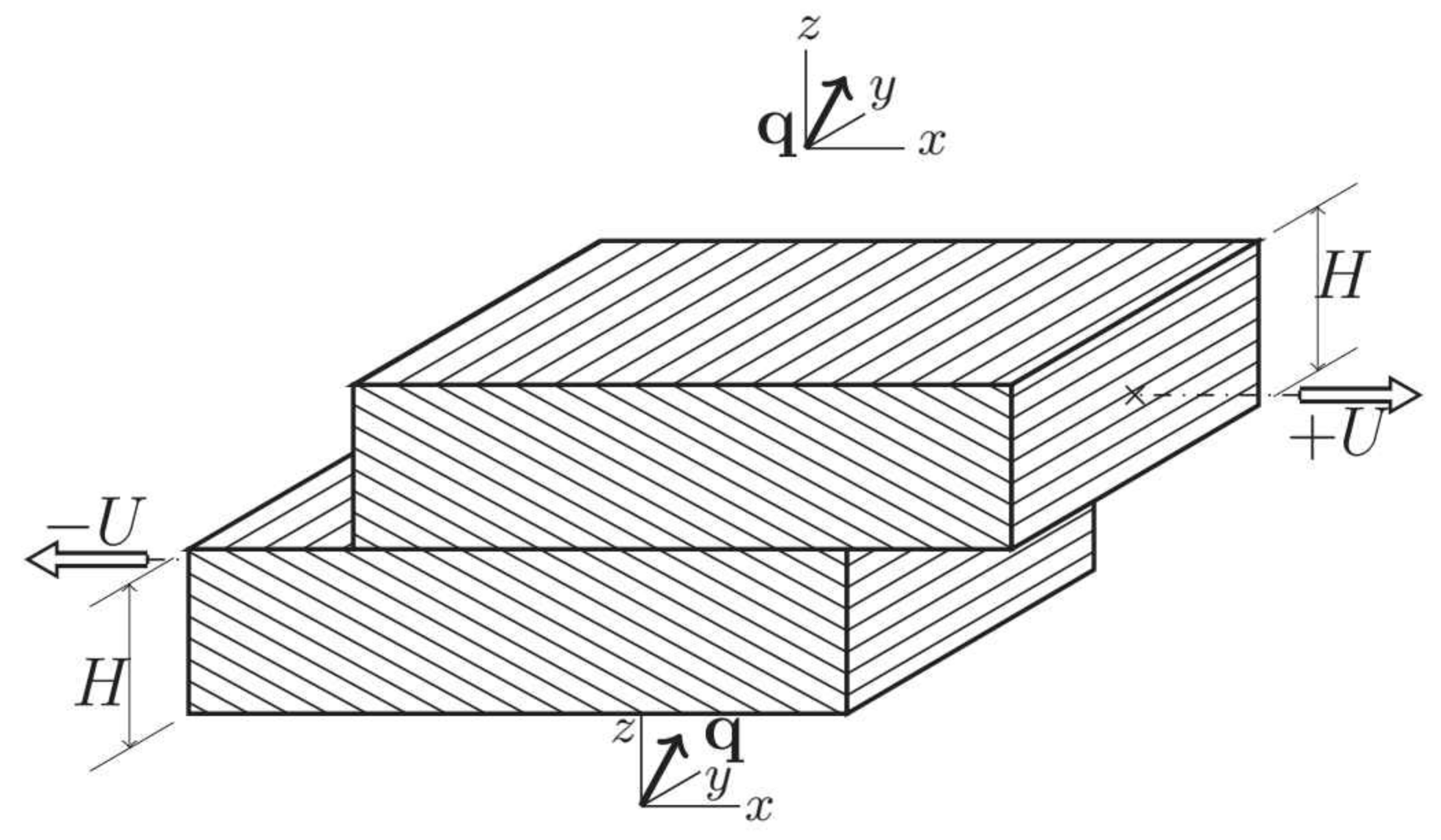 Two plates of anisotropic conductivity, sliding on top of each other, produce dynamo action.
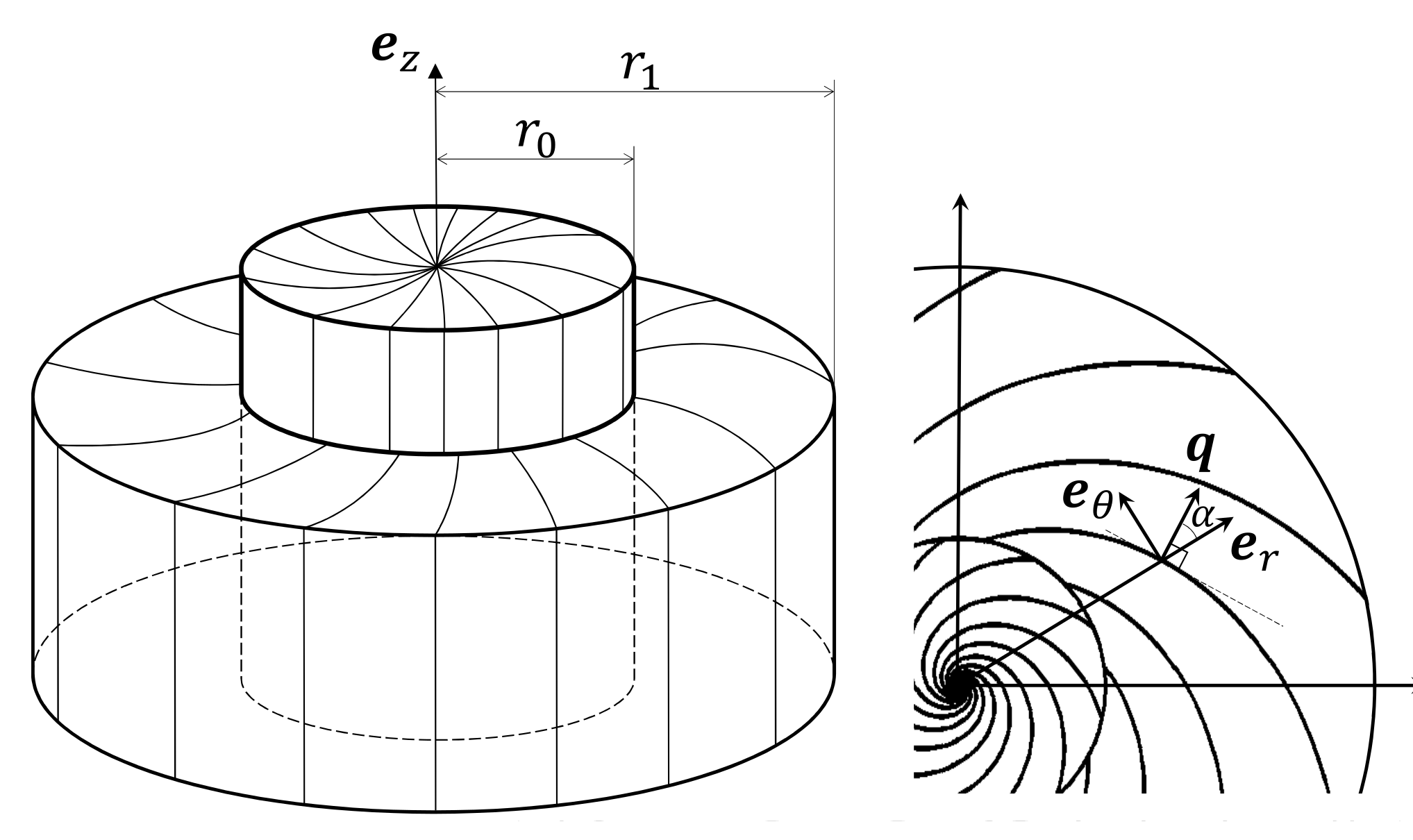 A rotor/stator configuration, of anisotropic conductivity, produce dynamo action.
Interestingly, these configurations can be solved analytically, which is rather convenient to understand the details of dynamo action. We have been interested in the behaviour at large rotation rates, of magnetic Reynolds numbers well above the critical rate above which dynamo action can exist. There were two types of dynamos: slow and fast. If you keep all parameters constant for a dynamo and only increase its electrical conductivity, how does the growth rate of the magnetic field depend on conductivity? If that growth rate becomes smaller and smaller, converging toward zero, than the dynamo is called a slow dynamo. If that growth rate converges toward a constant value, this is a fast dynamo. OK, then our dynamos are faster than a fast dynamo! The growth rate increases (unbounded) when the electrical conductivity increases. We called that new type 'very fast' or 'furious' dynamos (see PDF and PDF).
A rotor/stator configuration, of anisotropic conductivity, produce dynamo action.
Interestingly, these configurations can be solved analytically, which is rather convenient to understand the details of dynamo action. We have been interested in the behaviour at large rotation rates, of magnetic Reynolds numbers well above the critical rate above which dynamo action can exist. There were two types of dynamos: slow and fast. If you keep all parameters constant for a dynamo and only increase its electrical conductivity, how does the growth rate of the magnetic field depend on conductivity? If that growth rate becomes smaller and smaller, converging toward zero, than the dynamo is called a slow dynamo. If that growth rate converges toward a constant value, this is a fast dynamo. OK, then our dynamos are faster than a fast dynamo! The growth rate increases (unbounded) when the electrical conductivity increases. We called that new type 'very fast' or 'furious' dynamos (see PDF and PDF).
`Fury', a furious dynamo experiment
Based on these models, we have built an experimental version, called Fury. This is a rotor of finite length inside a stator of finite diameter. Below is a finite element model of the expected eigenmode. The view shows a meridional plane, the configuration and eigenvector are axisymmetrical. on the right, the expected profile of radial magnetic field is compared to the measurements on the dynamo itself.
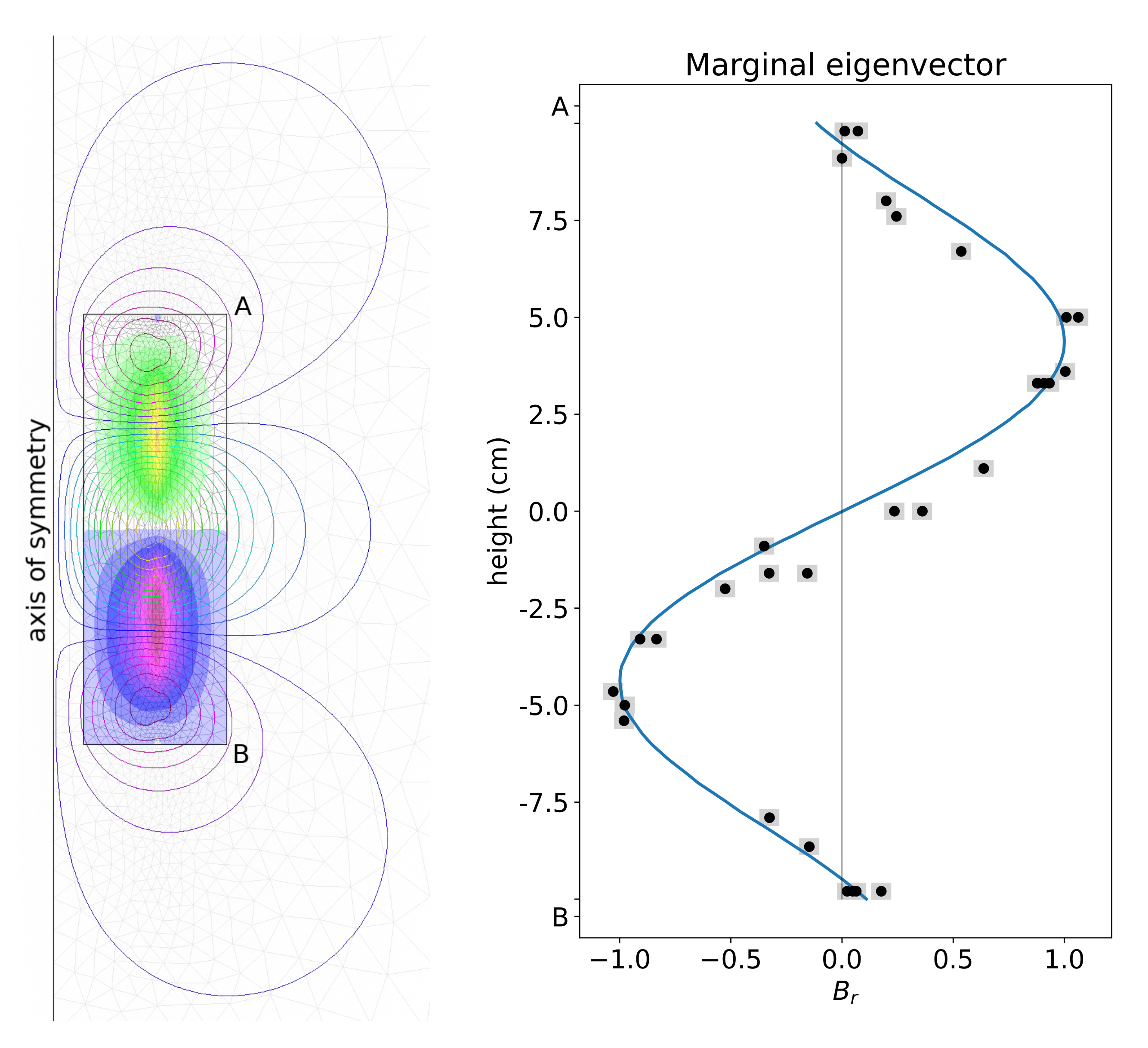 The maximum of the azimutal (toroidal) magnetic field (represented by color levels) coincide with the radius of the rotor. Of course, only the poloidal magnetic field can be measured outside the conducting domain. Some field lines are shown in the figure.
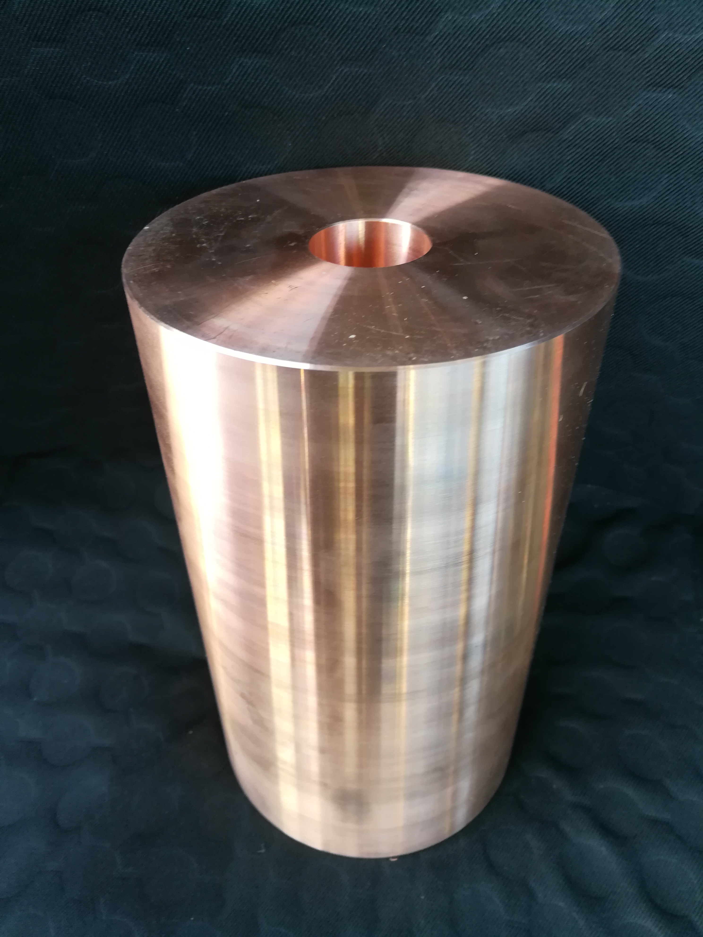
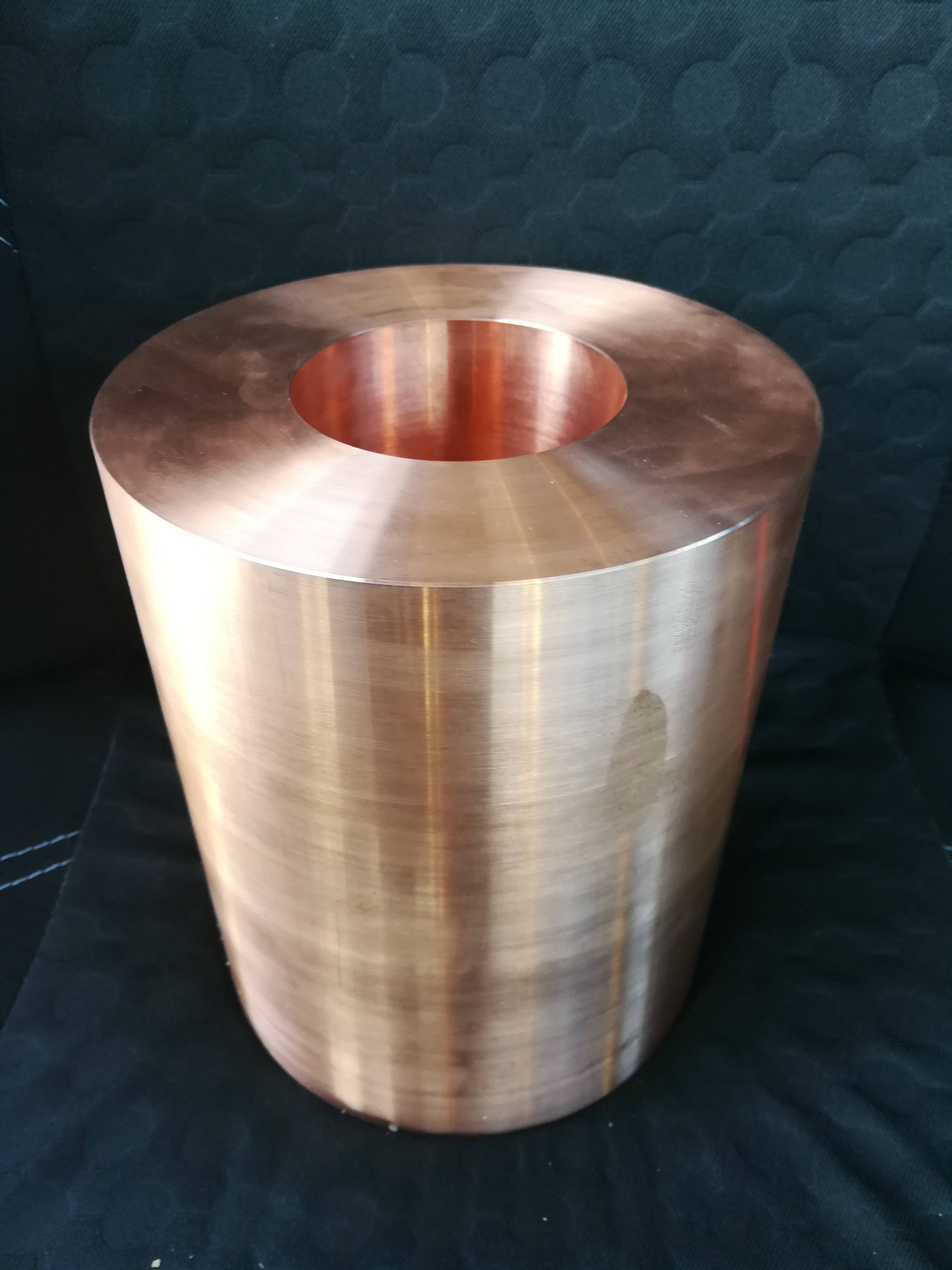
Now let's see a few steps for the construction of Fury. First, buy copper pieces
The maximum of the azimutal (toroidal) magnetic field (represented by color levels) coincide with the radius of the rotor. Of course, only the poloidal magnetic field can be measured outside the conducting domain. Some field lines are shown in the figure.
Now let's see a few steps for the construction of Fury. First, buy copper pieces
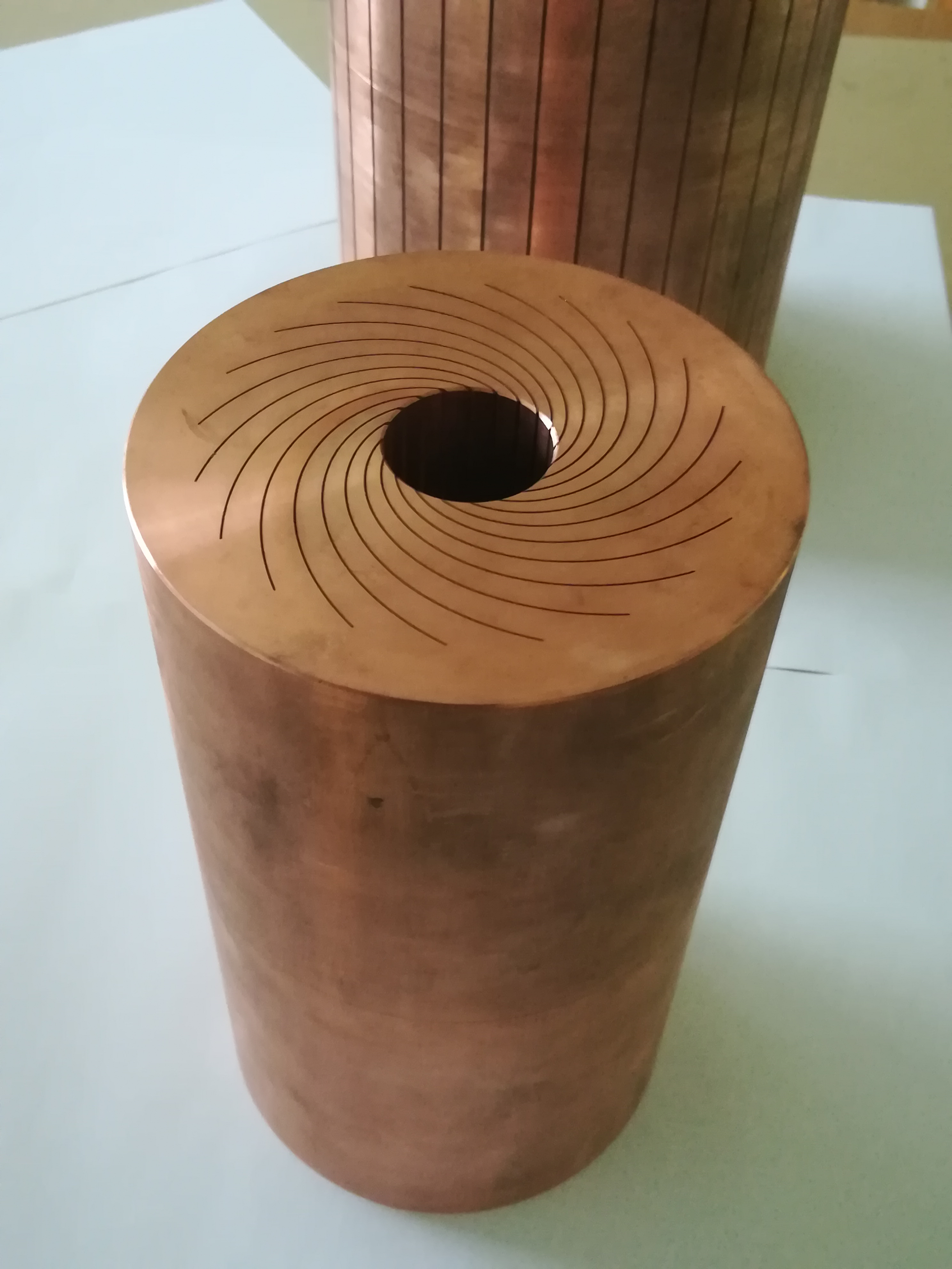
 Have nice grooves cut using electro-erosion, along logarithmic spirals.
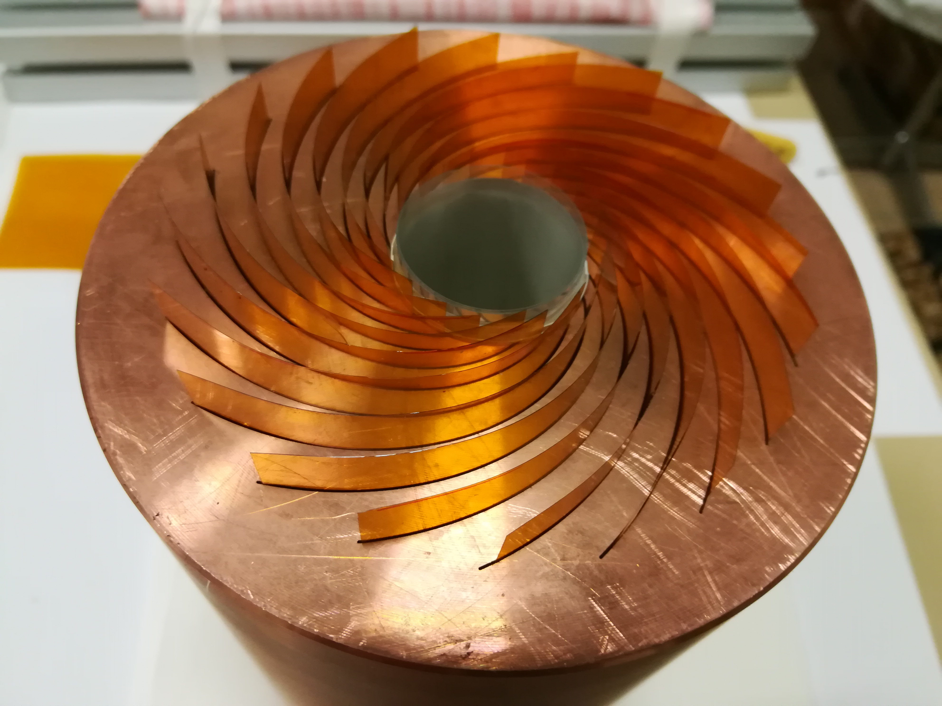
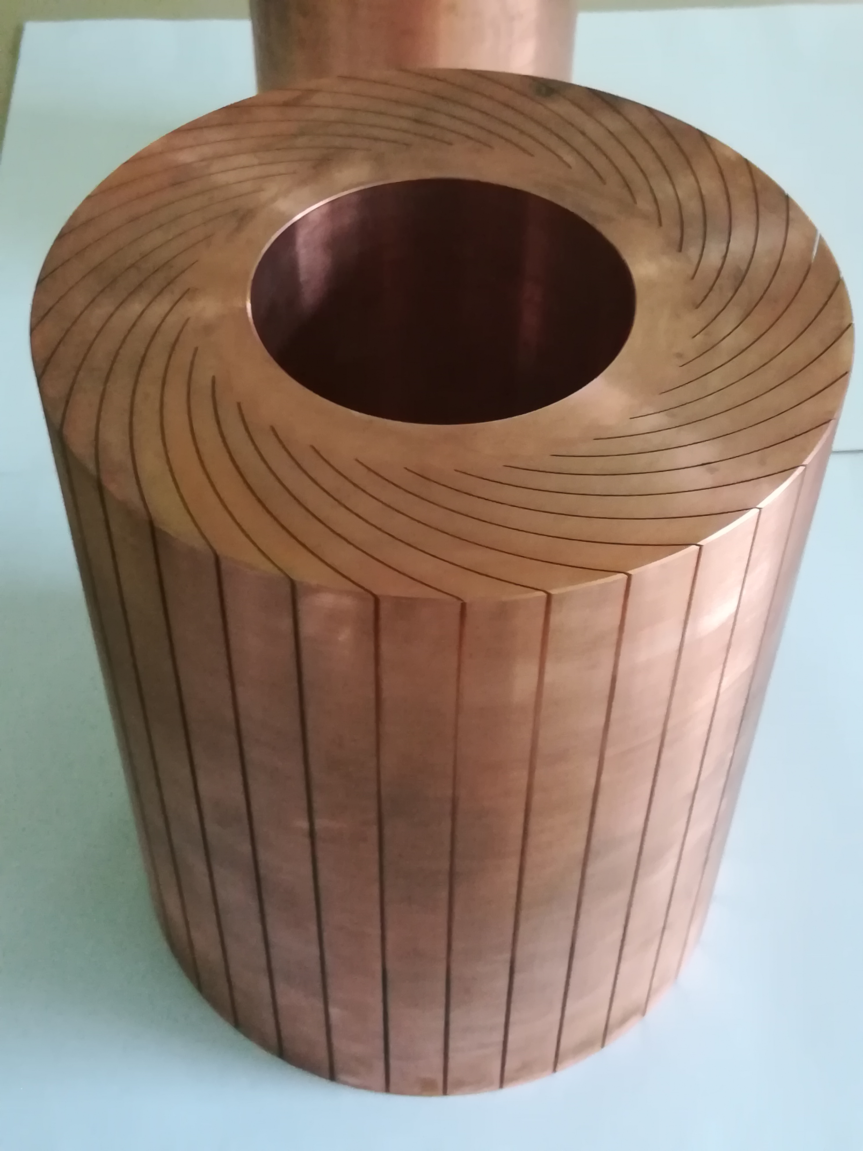 Put insulating films in the grooves. Fill them with epoxy for mechanical strengthening.
 Cut the extra copper. Have the internal cylindrical surfaces silver plated, for good electrical contact with galinstan. Put an axis in the rotor.
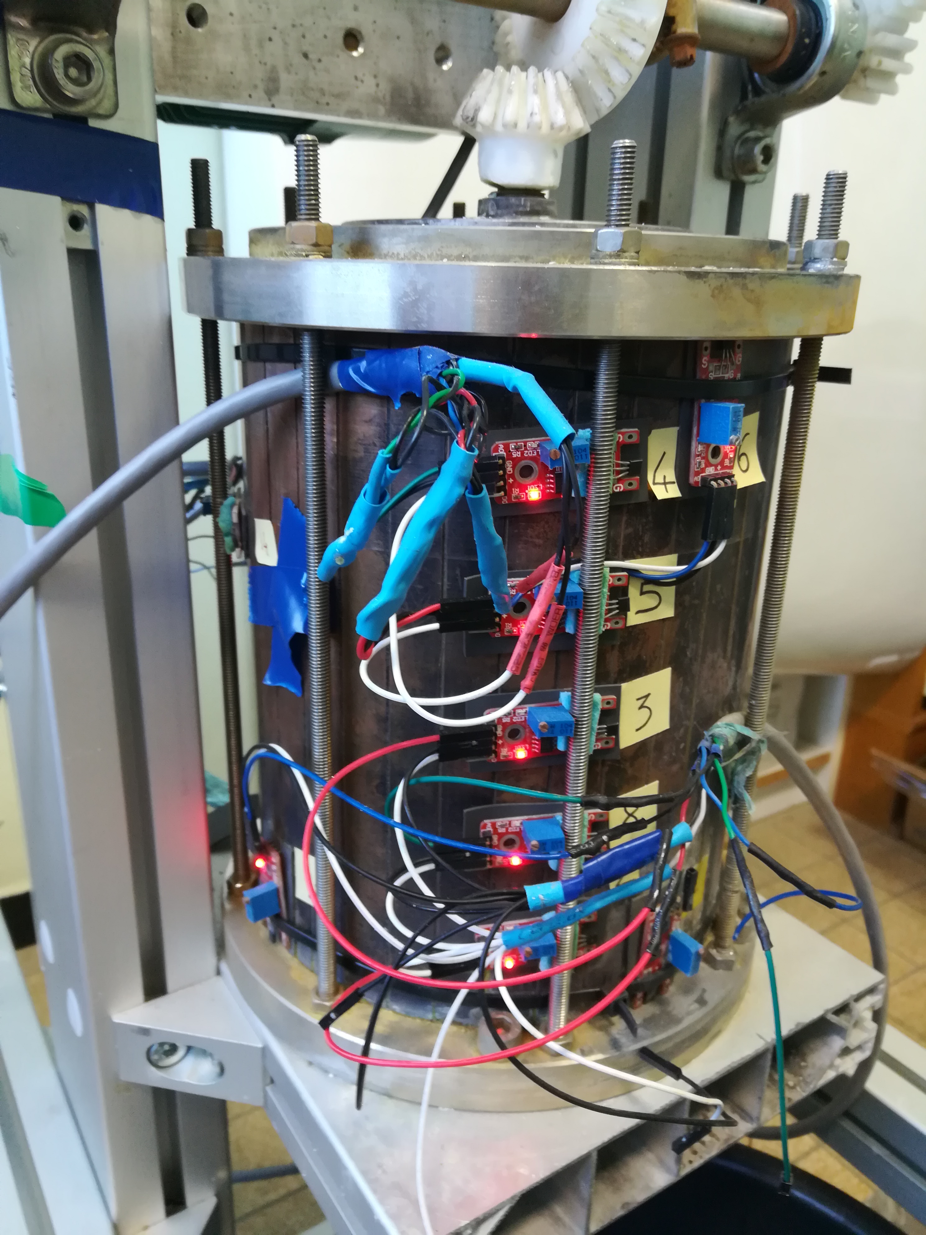
 Put the rotor inside the stator. Maintain stator, rotor and ball bearings with two flanges on top and bottom held together by threaded rods (OK, that photograph was taken before silver plating).
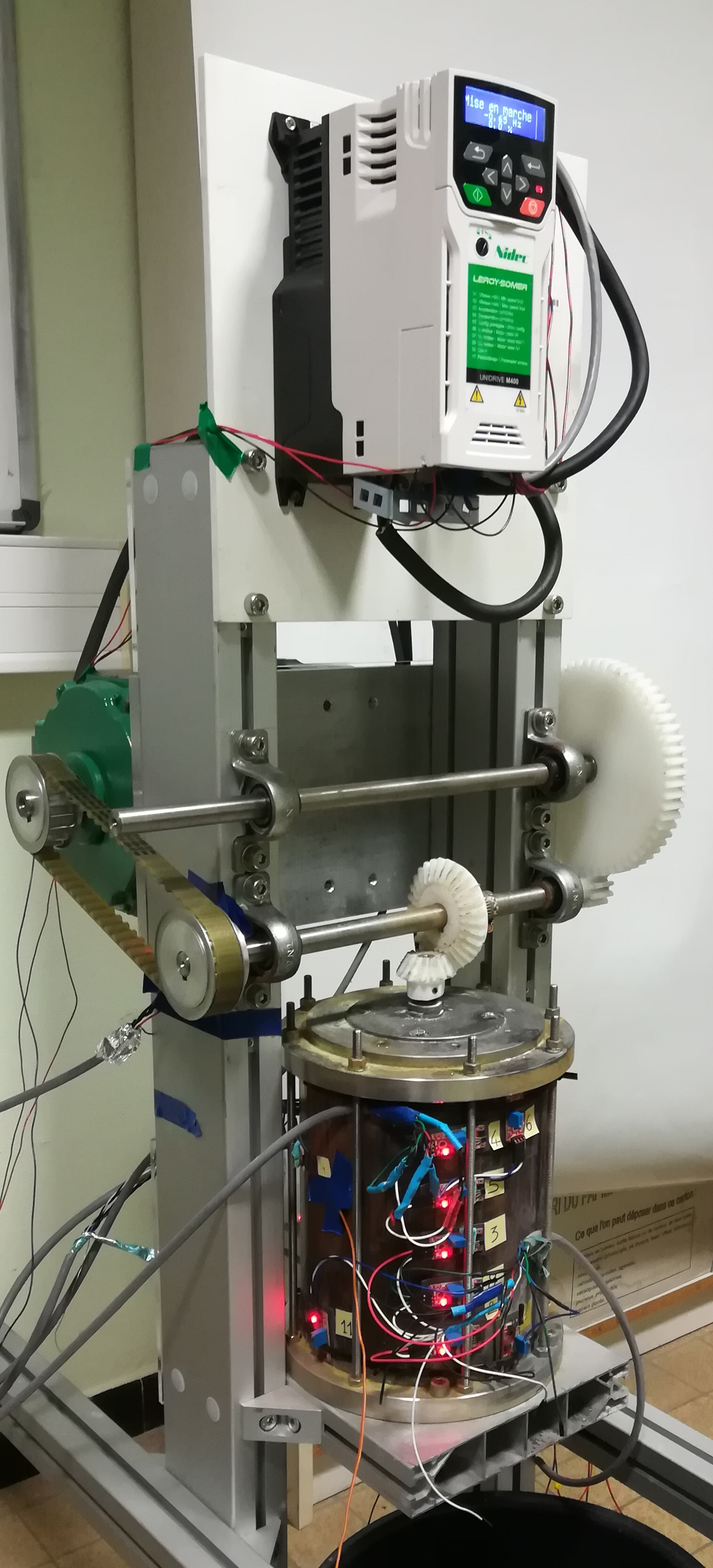
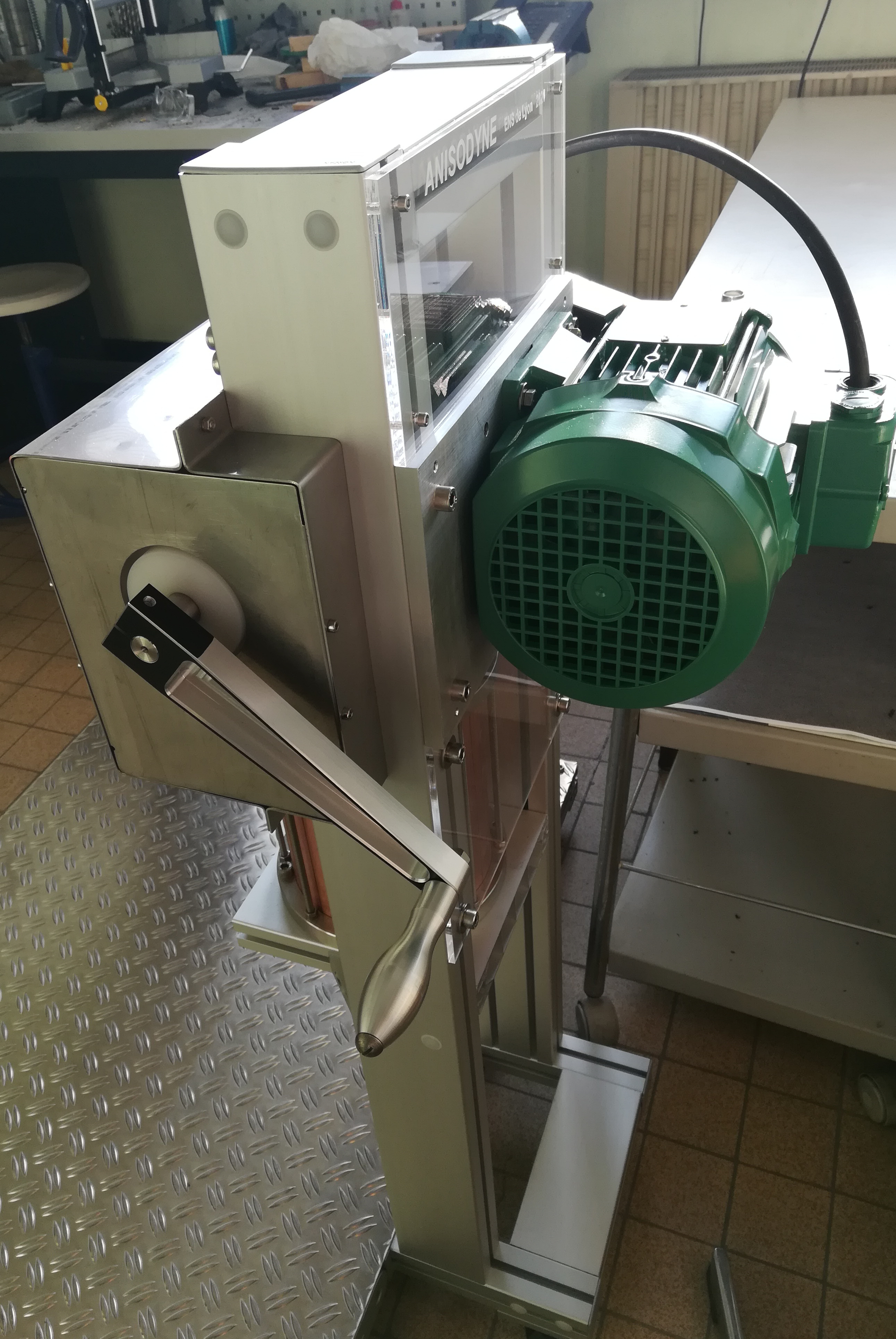
 Finally, install the experiment on an aluminium structure. Have gears, handle, and even an electric motor for running the experiment the easy way. Place Hall sensors for magnetic field measurement. It is ready!
![]()
![]()
 And, here is the very first successful run of the experiment Fury!
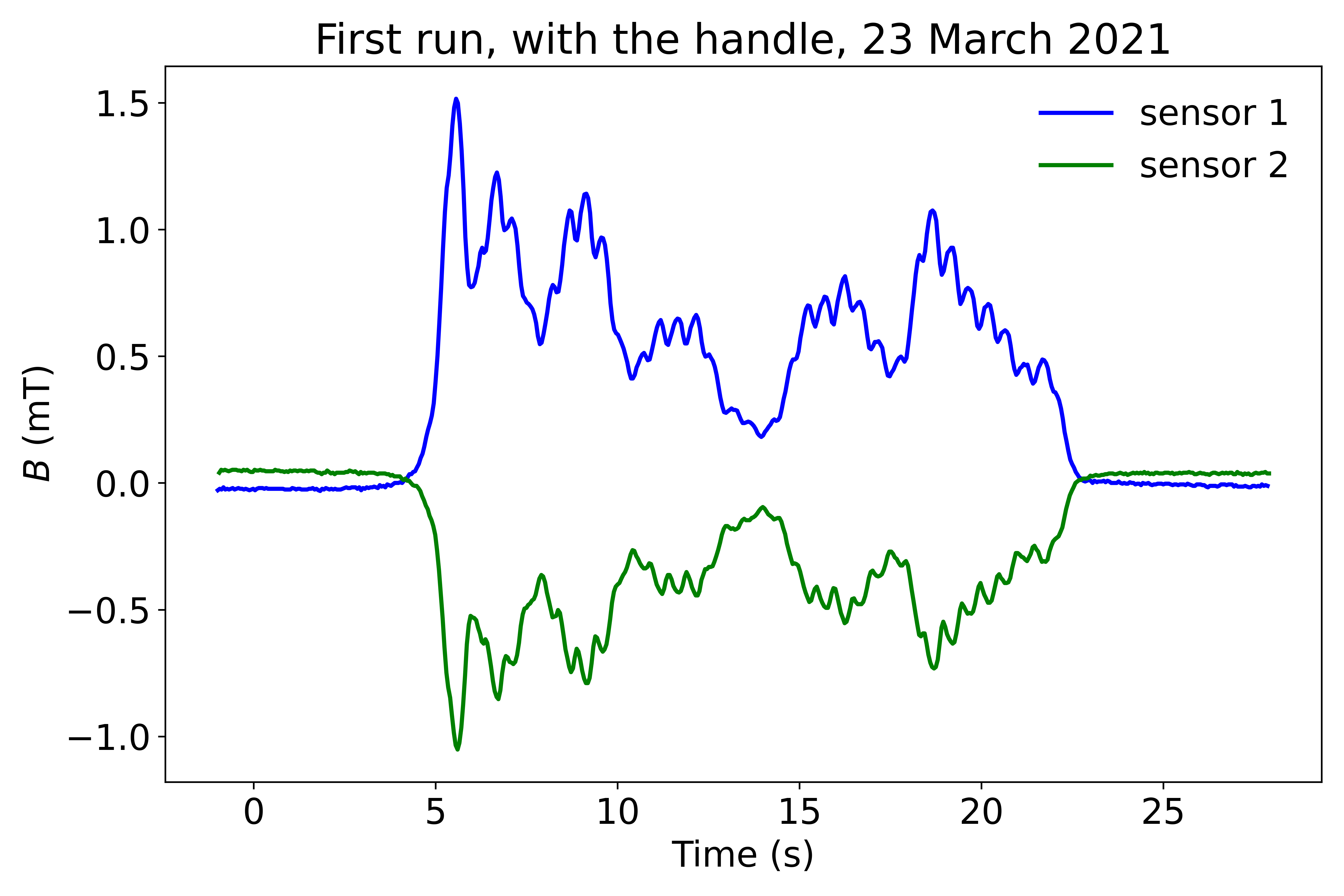 This measurement was obtained by rotating the handle. Each turn corresponds to 12 turns of the rotor. Dynamo action is obtained for 24 Hz, i. e. 2 Hz for the handle. On the signals of the magnetic field, the small oscillations correspond actually to the handle rotation frequency. The strength one exerts on a handle is larger when the arm goes downward and smaller when it goes up. For more complete results, including those obtained with the electric motor, see the manuscript PDF

Adrar, Mauritania